
Getting intimate with x86
That I may detect the inmost force
Which binds the world, and guides its course;
Its germs, productive powers explore,
And rummage in empty words no more!Goethe, Faust (tr. Bayard Taylor)
When you write a compiler, your work is usually done at a level somewhere around the generation of machine-dependent assembly. You really don’t want to go into how individual instructions are encoded, regardless of platform, because that is the assembler’s job. That is especially true for x86, because x86 instruction encoding is an entirely different can of worms from whatever you are doing.
But if you are like me, leaving cans of worms unopened is hard. I want to know “the poodle’s real core.” And so I wrote an x86 emulator. From scratch. To better understand x86 instruction encoding. That is a totally reasonable thing to do, right?
The result is x86rme. It decodes and executes real mode x86 instructions, one byte at a time. No libraries, no reference implementations, just me and the Intel SDM, “studied / from end to end, with labor keen; / and here, poor fool! with all my lore / I stand … not no wiser than before but actually having learned a thing or two that I hadn’t really been aware of.”
The opcode byte is not just an opcode byte
I like RISC-V. It is simple, it is regular, it is predictable. Fixed instruction size (if you ignore the “C” extension), four different instruction encodings, opcode always in bits 0 to 6. It makes me happy. But this is x86. It is not simple. It is not regular. It is most definitely not predictable. It has variable instruction size. It does not make me happy – but x86 does not care about my sensitivities and pretty much runs the world regardless.
Here is a color-coded map of x86 instructions. Usually you find these kinds of maps color-coded by instruction group, but I chose to group the instructions by encoding type. Same color, same encoding. If your reaction to this is “but that is all over the place!” then you have understood this table. Note that color-coding by encoding type is only meaningfully possible for 386, maybe 486-era instructions, as “modern” x86 with its 64-bit ISA and SSE extensions is orders of magnitude more complex than this.
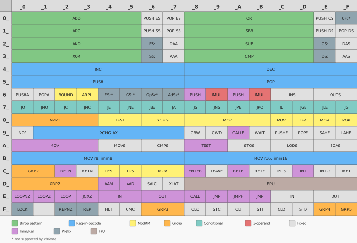
The binop pattern
Arguably the simplest encoding, and with 48 opcodes the second most common one. These are the arithmetic instructions, the bread and butter of every CPU, and they benefit from being only one byte long. A longer encoding would free up space in the opcode table, but having the most commonly executed instructions take up more bytes would make every program bigger. x86 encoding attracts a lot of mockery and criticism for being really hard to decode. And it actually really is. But the reason for being so complex is a series of brilliantly engineered tradeoffs made in the 1970s that pay off until today: squeezing remarkable functionality into 256 opcodes while balancing code density with decoder simplicity, and still leaving room for future extensions. We still use that ISA, five decades later.
Bits 7:6 are always 0, 5:3 select the operation, bits 2:0 select the operand form:
| Bits 5:3 | Operation |
|---|---|
| 0 | ADD |
| 1 | OR |
| 2 | ADC |
| 3 | SBB |
| 4 | AND |
| 5 | SUB |
| 6 | XOR |
| 7 | CMP |
| Bits 2:0 | Operand form |
|---|---|
| 0 | rm8, r8 |
| 1 | rm16, r16 |
| 2 | r8, rm8 |
| 3 | r16, rm16 |
| 4 | AL, imm8 |
| 5 | AX, imm16 |
Register-in-opcode
The most common encoding at 55 opcodes. Instead of spending a separate byte to
name a register, the register is packed into the low 3 bits of the opcode
itself. INC, DEC, PUSH, POP, XCHG AX, and MOV immediate all use
this scheme.
| Bits 2:0 | 8-bit (mov r8, imm8) | 16-bit (all other instructions) |
|---|---|---|
| 0 | AL | AX |
| 1 | CL | CX |
| 2 | DL | DX |
| 3 | BL | BX |
| 4 | AH | SP |
| 5 | CH | BP |
| 6 | DH | SI |
| 7 | BH | DI |
This is the same register numbering that appears in the ModRM byte’s reg and
rm fields, as we will learn soon.
The 8-bit column has a surprise: indices 4-7 do not map to the low bytes of SP,
BP, SI, and DI (which on the 8086 simply did not have individually addressable
halves), but to the high bytes of AX through DX. That means MOV AH, imm8 is
0xB4, not because AH is the “fourth register,” but because it is the high byte
of the register with index 0, offset by 4.
This encoding makes PUSH and POP single-byte instructions. That matters,
because every function prologue pushes BP and other registers, and every
epilogue pops it back. (At least until you enable compiler optimizations.
Because then this sentence gets more footnotes than x86 encoding has
exceptions.) Anyway: single-byte stack operations keep call overhead small, and
small is good.
By the way, did you spot NOP? Hiding at 0x90? You may ask, “why do you give
it that look, it didn’t do anything!”. Exactly. I believe it is quite common
knowledge, but let’s make it explicit: NOP is
actually just a nickname for XCHG AX, AX. Look it up in the table above, it’s
true! Exchanging a register with itself of course does nothing, and Intel’s
assembler canonicalized it to NOP. One fewer opcode to spend, one more
encoding trick.
The ModRM byte
Do you know these tax forms, where if you checked certain boxes, you need to attach a different form? And if you check certain boxes on that form, you need to attach yet another different form as well? That is how ModRM works in a nutshell.
Take for example the humble MOV instruction. There are many encodings for it,
but we’ll look at the instruction 0x8A that moves 8 bits of data and the
instruction 0x8B that moves 16 bits of data. Now where to move data from and
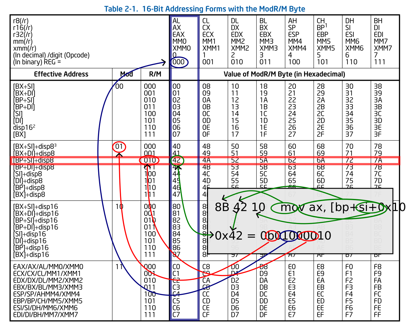
to? x86 ISA allows for a quite complex memory address scheme. mov ax,
[bp+si+0x10] is a valid instruction and means “copy 16 bits from the memory
location that is calculated by the value in register BP, plus the value in
register SI, plus a static offset of 16, into the AX register”. There is simply
no way of making all that information fit into whatever bits are left in the
first (and only) byte of the instruction. Which is why instructions like 0x8A
and 0x8B need another tax form attached more data attached: the ModRM byte.
The ModRM byte encodes both the source and the destination of an instruction,
as a pair. It describes one “register” (called r8 for 8-bit registers, r16
for 16-bit registers, and so on), and one “register or memory location” (called
rm8 for 8-bit register or data in memory, rm16 for 16-bit register or data
in memory, and so on). Which one is the source, and which one the destination,
depends on the instruction that the ModRM byte is for. For the very same ModRM
byte following an instruction:
- instruction 0x88 is
MOV rm8, r8, transferring data from a register to register-or-memory; - instruction 0x8A is
MOV r8, rm8, transferring data from register-or-memory to a register, i.e. the opposite direction.
The “register” is never encoded by its exact name, but rather its number. In
the earlier example of mov ax, [bp+si+0x10], the ModRM byte does not specify
the r as AX, but rather “Register 0”. Whether that means “AL”, “AX”, “EAX”,
“MM0”, or “XMM0” is again up to the instruction. If the rm part of ModRM
specifies a register (in this example it does not, but it could) then here too
the register is specified by number and the exact register is dependent on the
instruction.
Now let’s look at the rm part of the ModRM byte, which is [bp+si+0x10] in
our example. There is no encoding for “content of address BP-plus-SI-plus-16”.
If there were, the ModRM byte would need to be much bigger than a byte, as the
offset (or “displacement”) can be any 8-bit or 16-bit number. There is an
encoding for “content of address
BP-plus-SI-plus-some-8-bit-value-that-I-will-tell-you-later” though. That 8 bit
value is then attached to the ModRM byte, as the ModRM byte is attached to the
MOV instruction, bringing the encoding for mov ax, [bp+si+0x10] to a total
of three bytes: 8B 42 10. Had we chosen a different rm in the ModRM byte,
say for example “BP-plus-SI-without-additional-offset”, there is no offset to
attach and the instruction mov ax, [bp+si] is only two bytes long: 8B 02.
And you thought taxes were hard, did you?
Luckily for us, the topic ends here, since this post only covers 16-bit
addressing used in real mode. 32-bit addressing, protected mode and long mode,
use an entirely different decoding table for the ModRM byte and another tax
form byte that can optionally be appended, the SIB (“Scale, Index, Base”)
byte. This allows for pretty much arbitrary scale, index and base registers. In
16-bit addressing, we are limited to certain combinations of BX, BP, SI and DI
registers.
Instruction groups: one opcode, many operations
We have seen that instructions like MOV can have multiple entries in the
instruction map. And now we will look at single entries in the map that
represent multiple instructions. Because that is perfectly normal. Mocking x86
never gets old.
Group 1: binary operations
Were you proud when you understood the ModRM byte? I have kind of bad news for
you. I lied. The reg field? The one that selects the register number? It
doesn’t just do that. For some instructions, for example those in group 1, it
is an index into an array of operations, to specify which binary operation
the instruction should perform:
| Reg | Instruction | Operation |
|---|---|---|
| 0 | ADD |
addition |
| 1 | OR |
bitwise or |
| 2 | ADC |
addition with carry |
| 3 | SBB |
subtraction with borrow |
| 4 | AND |
bitwise and |
| 5 | SUB |
subtraction |
| 6 | XOR |
bitwise exclusive or |
| 7 | CMP |
subtract, set flags, discard result |
Group 2: shifting and rotating
Same idea as Group 1: shift or rotate a value by either 1 bit, by the amount in register CL, or by an attached constant.
Shifting moves bits left or right. Bits that fall off one end are lost, and
zeros (or copies of the sign bit, for arithmetic right shift) fill in from the
other end. Rotating does the same, but wraps the bits that fall off back around
to the other side instead of discarding them. There are eight slots for four
shifts and four rotates, but only seven distinct operations: arithmetic left
shift and logical left shift both shift in zeros from the right, so SHL and
SAL are aliases that share one slot.
Group 3: unary operations. but also binary operations?
The group at 0xF6 and 0xF7 (for 8-bit and 16-bit values) could be so nice and regular, but alas, it isn’t:
- Only seven operations are defined:
TEST,NOT,NEG,MUL,IMUL,DIV, andIDIV. Operation 1, situated betweenTESTandNOT, is undefined. - Operation 0,
TEST, has a constant following the instruction. Just to check whether you were paying attention when you implemented your decoder.
Group 4: let’s cram all the misfits together
This is where things get truly ridiculous: INC, DEC, for incrementing and
decrementing values; CALL, CALLF, JMP, and JMPF for flow control, which
has nothing to do with incrementing; and last but not least PUSH to store
values on the stack. Quite frankly: it is such a mess that I would like to
kindly direct you to the source code in lib86rme.cpp for any attempt to make
heads or tails of this.
Conditional
Check the FLAGS register and jump. Or not, simple as that. Note that there are
16 instructions but only 8 conditions: every odd instruction is the negated
form of the even instruction before it. Some instructions have multiple names,
e.g. JZ for “jump on zero” and JE for “jump if equal”. Remember the CMP
instruction that compares two values by subtracting one from the other: If the
values are equal, the result is zero. This becomes more visible if you rewrite
a condition like if (foo == bar) { ... } into if ((foo - bar) == 0) { ...
}.
There is more equivalences, but they are of the more ordinary kind: for example, “jump if greater than or equal to” is identical to “don’t jump if less than”:
- 0x70:
JO(jump if overflow) - 0x71:
JNO(jump if not overflow) - 0x72:
JB(jump if below),JC(jump if carry),JNAE(jump if not above or equal) - 0x73:
JNB(jump if not below),JNC(jump if not carry),JAE(jump if above or equal) - 0x74:
JE(jump if equal),JZ(jump if zero) - 0x75:
JNE(jump if not equal),JNZ(jump if not zero) - 0x76:
JBE(jump if below or equal),JNA(jump if not above) - 0x77:
JNBE(jump if not below or equal),JA(jump if above) - 0x78:
JS(jump if sign) - 0x79:
JNS(jump if not sign) - 0x7A:
JP(jump if parity),JPE(jump if parity even) - 0x7B:
JNP(jump if not parity),JPO(jump if parity odd) - 0x7C:
JL(jump if less),JNGE(jump if not greater or equal) - 0x7D:
JNL(jump if not less),JGE(jump if greater or equal) - 0x7E:
JLE(jump if less or equal),JNG(jump if not greater) - 0x7F:
JNLE(jump if not less or equal),JG(jump if greater)
The two sets of inequality operators (above/below and greater/less) compare signed and unsigned values respectively.
Three operands
x86 is the Dadaism of ISAs. Every rule needs to be deconstructed, subverted, an exception defined, with just enough rules so that even the exception gets its own exception. And now it is time to undermine the “two arguments” rule.
Up to now, all instructions had two arguments, one typically called “destination”, one typically named “source”. For operations that take two source arguments, for example “C = B + A”, the first source argument is implicitly the destination argument, so more like “B = B + A”. That makes it nice and regular and saves the space required to specify a third operand.
To break up that monotony and to make sure you don’t get bored, IMUL does
away with that rule and expects an additional 8-bit or 16-bit constant after
the instruction for “reg = rm * constant” semantics. Ain’t. That. Fun. Also
note that the 8-bit and 16-bit variants don’t even have the decency to live
next to each other, but rather live as opcodes 0x69 and 0x6B.
Immediate / Relative
A ray of hope and sunshine in the x86 jungle! Just an instruction, followed by a constant. You still need to know whether it is an 8-bit or 16-bit constant though. That would have been too easy, even for the easy part.
The relative addresses used in JMP and CALL instructions are relative to
the end of the instruction. jmp 0 is a two-byte NOP, jmp -2 (or jmp
0xfe) is an endless loop.
Prefixes
If “Immediate / Relative” encoded instructions are a ray of sunshine, prefixes
are the inevitable clouds. You remember the mov ax, [bp+si+0x10] example? We
can make it more complicated. In real mode, memory addresses consist of a
16-bit segment and a 16-bit offset, with the linear address calculated as “16 *
segment + offset”. But which segment value are we using in that example?
Memory addresses calculated based on the IP register use the CS segment.
Addresses calculated based on BP or SP use the SS segment. Everything else uses
the DS segment. Now how would you like a special “prefix” “instruction”, that
changes the implicit segment for the next instruction and introduces state into
your instruction decoder, and ambiguity for what should happen if an
instruction that doesn’t even access memory follows? What happens if you keep
on stacking prefixes? That’s what the prefix “instructions” at 0x26, 0x2E,
0x36, and 0x3E do. mov ax, [es:bp+si+0x10] becomes 26 8B 42 10, and
prefixes for non-memory instructions are ignored. Except when they aren’t.
Cloudy enough or ready for one more? The REP group of prefixes will make the
instruction execute as many times as is specified in register CX. Or until the
zero flag is set, in the case of REPZ and REPNZ. But only for the string
instructions 0xA4..0xAF. Everything else will fail.
And finally, the LOCK prefix. It asserts the bus lock signal for
multi-processor synchronization. You could even double-, triple- or
quadruple-lock your instructions by prepending more than one LOCK prefix
byte, but unexpectedly that does not change the behavior. A missed opportunity,
given how wild this instruction set is already, but maybe Intel will define
semantics for that in the future. On a single-CPU emulator in real mode, it
does nothing. x86rme parses it and moves on.
FPU
Opcodes 0xD8 through 0xDF belong to the 8087 floating point coprocessor. On the original 8086, these were handled by a separate chip that sat next to the CPU on the motherboard, listening to the instruction stream and executing floating point operations in parallel. The 486 finally integrated the FPU into the CPU itself, but the encoding still reflects that two-chip heritage.
x86rme currently does not support FPU instructions. Dealing with those is a project in its own right.
Summary
Luckily, not all of x86 is as scary as I have described above, and even the more complex instructions do not require Faustian Witch-Sabbath Magic to understand. Most instructions are simple, single bytes.
I have learned a lot from this endeavor, getting my hands dirty and really up-close and personal with the instruction set that is so pervasive. But for now, I’m done rummaging, and after all, there is this poodle here, that wants to be let out the door…
The code is on GitLab.